DIODE BOARD
INSTALLATION INSTRUCTIONS
IMPORTANT: READ THE PRECAUTIONS ON PAGE 4 BEFORE INSTALLATION. FAILURE TO DO SO COULD RESULT IN DAMAGE TO YOUR ELECTRICAL SYSTEM. READ THE FOLLOWING CAREFULLY BEFORE INSTALLATION.
This board is 100% compatible with the factory diode boards used with the Bosch alternators fitted to all air cooled Boxers. There are some mechanical differences between this board and the factory board, and some of the electrical connections are found in different positions on this board. Read the section on installation to understand these differences. Diode boards fitted to bikes with the early (180 watt) alternators were superceeded by a different diode board for use with later systems. The later board had an additional ("Y") connection from the alternator to the diode board. The later board may be used on earlier systems, but not visa versa. This board is suitable for all types of alternators. Due to slight differences in engine design the following should be noted before installing this board.
.
R75 and similar with solid cast board mounts.
The new diode board is slightly thinner than the factory board and may cause the existing allen screws to bottom out in the threaded mounting holes. Shorter bolts are provided with this board to overcome this problem In addition, the harness from the alternator to the diode board had a molded housing holding the three connectors. This harness should either be replaced with a later harness where the three connectors are not in a molded housing, or the molded housing holding the three connectors should be carefully cut away from the connectors.
Boards with rubber mounts.
These boards are fitted with a ground wire with one end mounted underneath one of the diode board mounting holes, and the other bolted to the engine case. This should be removed and the supplied ground wire used in its place, as described in the installation instructions. Engines with solid metal mounts do not need this ground harness.
1. DISCONNECT THE BATTERY BY REMOVING ONE BATTERY TERMINAL OR DISCONNECTING THE BATTERY GROUND WIRE AT THE GEARBOX. Failure to do so will result in electrical damage when the front cover or diode board is removed.
2. Remove the cover from the front of the engine exposing the diode board at the front/top of the engine.
3. Remove all accessible connectors from the diode board. Be gentle, do not pull hard on the wires but work any tight connectors off by rocking sideways. Make a note of which connectors on the board these were removed from.
4. Remove the four screws or nuts holding the diode board to the engine. Be careful not to lose the washers. Inspect the condition of the rubber mounts if used.
5. Gently pull the diode board away from the engine, and remove the wires from the rear of the board. Make a note from which connectors they were removed.
6. Study the diagrams at the end of this description, comparing the new and old connections. You will note that some of the terminals that were on the rear of the board are now at the front. 6-A. For rubber mounted boards remove the existing ground wire(s) from the engine case and connect the supplied ground wire to the same engine case bolt.. Please refer to "IMPORTANT PRECAUTIONS" at the end of this document.
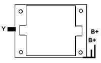
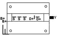
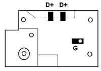
7. Holding the new board, make any required connections to the rear of the board. These consist of one or two wires at the top of the new diode board (some bikes used both connectors, some only one). These are labelled "D+" on the diagram and are probably blue in color.
7-A. For rubber mounted boards connect the ground wire to the ground connector on the rear of the board.
8. Mount the diode board to the engine using the 4 nuts or allen screws (supplied) and washers, ensuring that no wires are trapped between the board and the case. Please refer to "IMPORTANT PRECAUTIONS" - paragraph (2) on page 4 if aftermarket solid mounts are used. For earlier engines with board mounting pillars cast as part of the engine case, it is necessary to use the mounting screws supplied as the existing screws may bottom in the threaded holes and the board will not be firmly mounted.
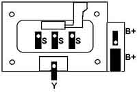
9. Connect the remaining wires to the board as follows: 9.1 Connect the black three wire harness to the front of the board. Note that the sequence of these three connectors is not important as long as all three are connected between the stator and the diode board. Earlier harness in molded housings will either need to be replaced by later harnesses or the outer case removed. 9.2 On bikes fitted with later alternators connect the black "Y" connector on the stator to the connector at the bottom of the diode board. Earlier systems did not use this connector. 9.3 Connect the heavy red wire to the positive terminal at the right side of the board marked "B+". Some systems have a wire going to the second positive terminal. If so connect this also.
10. Replace the front cover, ensuring that all wires are clear of the cover. Reconnect the battery.
11. Installation is now complete. Start engine and check that charging light operates correctly.
|
CONNECTOR LOCATIONS
|
|||
|
Connector |
Factory board
|
Thunderchild |
|
|
B+
|
2
|
front right
|
front right
|
|
Y
|
1
|
front left
|
front bottom
|
|
S
|
3
|
rear middle
|
front center
|
|
D+
|
2
|
rear middle
|
rear top
|
|
G
|
0/1
|
via bolt holes
|
rear
|
IMPORTANT PRECAUTIONS: READ THIS BEFORE INSTALLATION. FAILURE TO DO SO COULD RESULT IN INCORRECT INSTALLATION OF THE DIODE BOARD AND POSSIBLE ELECTRICAL SYSTEM DAMAGE. IF YOU ARE NOT SURE WHETHER IT APPLIES TO YOU CONTACT US FOR MORE INFORMATION.
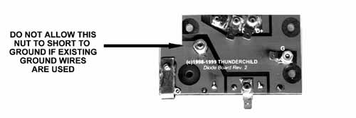
1) When rubber mounts are installed, a ground wire is used to make the connection between the board and the engine case. With the new board it is recommended that you remove the existing single or double connection ground wire and use the supplied heavy duty ground wire. If you chose to keep the existing ground wire in place, it is imperative that the lug on the ground harness does not touch the positive diode module mounting bolt when the board is tightened in place (see illustration). This will cause a short to ground when the battery is reconnected.
2) Some bikes have been fitted with aftermarket solid board mounts in place of the factory rubber mounts. It is possible that if these are over 1/2 inch in diameter there could be an electrical problem when the board is mounted. We have not come across any aftermarket mounts that exceed this size, but some home made mounts could have this problem. This does not apply to engines with solid mountings cast as part of the engine case.