TECHNICAL
INFORMATION
|
|
|
TECHNICAL |
|
|
|
||||||||||||||
Alternator Calculations
or
How Long Will My Bike Run With All the Stuff I've Got On It
|
There is often concern over the capability of the charging system on the BMW twins. The alternators on all but the earlier twins (70's) are rated at 280 watts. This means that the maximum current available from these units is about 20 amps at 14 volts. If any more current is drawn from them the voltage will drop to less than 14 volts resulting in their inability to keep the battery charged. Furthermore this maximum output is only delivered at fairly high rpm (about 3500) due to the fact that the alternator rotor is connected directly to the crankshaft (rather that driven via a belt as on a car engine with a gearing up in rpm of at least 2 to 1). In calculating how many accessories may be added to your bike it is not sufficient to simply assume that 280 watts is available. If most of your driving is around town with frequent stops at intersections and stop lights then you must take into account the time when the alternator is supplying no power and all power is being supplied from the battery. It is surprising when driving around a city how little time is spent running at 3000 rpm vs. spent sitting at traffic lights. Let us try
a couple of examples. In these examples we will be referring to
the current used not the wattage.
|
A
fully charged 20 amp hour battery could therefore run this system
without charging for about 2.8 hours (20 amp hours divided by 7.2
amps = 2.78 hours). So if you find yourself away from home with
a dead charging system your bike could probably run for a little
over 2 hours assuming no other accessories were installed. This
also assumes you don't use the brake too much as it draws about
2 amps or the turn signals at about 2.5 amps. And avoid using the
starter.
If you disconnect the headlamp and tail lamp however you could probably run for over 6 hours (20 amp hours divided by 2.9 amps = 6.9 hours).
So far so good...... With extra lights and a heated vest this problem gets even worse. It's time to do your own math... |
A Word About Voltage Regulators
| The higher the voltage across the battery the faster it will charge. There is a top limit of about 14.5 volts beyond which the battery can become damaged from overheating (the exact voltage depends on temperature, state of charge etc). Many BMW twins are fitted with voltage regulators set at 13.8 or 14.0 volts. Our fixed voltage regulators (often called high output regulators) are set at 14.3 volts which will result in faster charging thereby 'topping the battery up' faster between those stop lights. At the price this is a good addition to your system if you don't have already. |
Our variable voltage regulators can be set to almost any voltage to fine tune the system, but be warned that too high a voltage can cause damage to the battery and other electrical components. Bear in mind that the voltage regulator is really a voltage limiter. It prevents the voltage from the alternator exceeding a certain voltage which would cause damage to the battery and other electrical components. The voltage regulator cannot increase the output at low rpm. That is a function of the alternator stator and rotor design. |
How to Test the Ignition Module
|
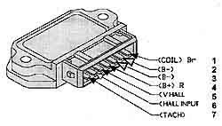
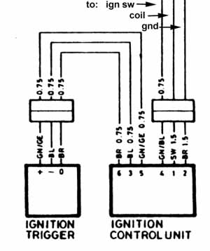
The ignition system of a bike equipped with electronic ignition consists if three major parts: the coil, the ignition trigger (can), and the ignition control unit (often called the ignition amplifier). The coil is usually easy to test, but verifying whether the trigger or the control unit has failed can be a bit more tricky. Referring to the extract from a wiring diagram one can see that three wires go from the control unit to the ignition module. Two are positive (power - pin 5) and negative (ground - pin 3) power, the third being the trigger wire (pin 6). Each time the trigger goes to ground a spark should be generated in the coil.
Testing the control unit therefore should be as simple as powering the unit up and grounding the trigger wire. The procedure is as follows: 1) Unplug the connector that connects the harness from the trigger unit to the harness from the control unit. Be careful as there is a small wire spring clip holding the connector together. 2) Remove one plug from the engine, reconnect the ignition wire and lay it on the cylinder such that the plug body is grounded and you can see the spark gap. 3) Stick a pin or fine wire into the center connector of the connector coming from the control unit (the one unplugged in step 1). |
4) With the ignition switched on, momentarily ground the pin/wire coming from the center connector. Each time you do this you should get a spark at the spark plug. This will indicate that the control unit is operational. Do remember however that it is not unheard of for the amplifier (or any other piece of electronics for that matter), to operate perfectly when cold and fail when warm/hot.
The above is copied from a full wiring diagram. Although not drawn in the diagram, the trigger wire (to pin 6 of the unit) really is the center connector.. |
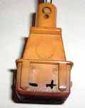
Want to Test the Ignition Trigger Can??
This takes a bit more electrical equipment and knowledge but here goes.........
|
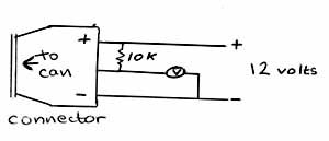
The ignition can contains a Hall effect sensor, a magnet, and a slotted metal cylinder which rotates between the magnet and the sensor. This causes a voltage on the output pin to vary thereby triggering the input pin of the ignition control unit. Note the diagram showing how to wire the connector off the bike for testing. The unit is powered from a 9 to 12 volt power supply (battery), and the output from the sensor (center pin) is pulled high through a 10 kilohm resistor. As the shaft on the cannister is rotated, voltage from the center output pin will fluctuate between a few millivolts and V+ (9 to12 volts). If this makes sense to you, go for it. If it doesn't then it might be wise not to invite trouble. With the unit on the bike, you can test this unit by carefully locating the center wire and connecting the voltmeter between this wire and ground. A useful way to make the connection to the wire is by sticking a pin through the insulation until it makes contact with the wire inside. Be careful that the pin does not touch the engine case. With the engine cranking you should see the voltage on the meter fluctuate at the sensor switches on and off. Remember that this will not show up intermittent or heat related faults. Good luck
|
|
Simple (but accurate) Diagram of Boxer Charging System
|
This diagram should give you all you need to diagnose most basic charging system problems. |
|
|
Referring to the diagram: With the ignition on (switch closed) and the engine off current flows from the battery, through the charge light, the voltage regulator and the rotor to ground. This provides the initial excitation (magnetization) to the rotor to get the alternator working when the engine is started. If the rotor is open (broken wire), the brushes worn out, the charge lamp burnt out or some other fault in this circuit, curent will not flow, the charge light will not illuminate and the alternator will not operate correctly. With the engine on and running fast enough for the alternator to produce a voltage above that of the battery (ie it is charging), the voltage at the B+ and D+ terminals of the diode board are equal. Because of this no current will flow between the D+ and B+ terminals and the charge light will be extinguished. Current from the B+ terminal will go to charging the battery and current from the D+ terminal will be available (via the voltage regulator) to magnetize the rotor. As the rpm drops, the alternator will not produce sufficient voltage to charge the battery and the voltage at the D+ terminal will drop below the voltage of the battery. Because the B+ terminal is tied directly to the battery, its voltage will be maintained at battery voltage. |
The voltage at the battery is now higher than the D+ voltage and current will therefore flow from the battery through the charge lamp, the voltage regulator and the rotor to ground and the charge lamp will again light. As the RPM increases the voltage at D+ again increases until it equals battery voltage and the lamp again goes out. When the voltage at the D+ terminal (which is equal to the B+ terminal if the voltage is above the battery voltage) exceeds a specified voltage, the voltage regulator cuts power to the rotor, reducing its magnetism thereby limiting the maximum voltage output from the alternator to a safe value. From this you can understand the common test for the voltage regulator. Remove the regulator, and short the DF and D+ terminals in the plug. With a voltmeter across the battery, does the voltage increase to 14.5 volts and more as the RPM's are increased? (Stop at 15 volts as damage can result). This test works because the voltage regulator is out of the circuit - remember that the voltage regulator is really a voltage limiter. |
|
Wire colors (most probable): DF
regulator to stator - BLUE/BLACK or BLACK
D+ diode board to regulator - BLUE D- regulator to ground (usually grounded on brush holder) - BROWN |
|
|
|
|
Strange electrical problems.......
|
R75/5 - Charging light failed, now the starter won't work...... |
|
|
Had a guy phone here hoping I could help with this problem on his R75/5. Basically his starter wouldn't work, and after replacing the starter protection relay, he was preparing to replace the starter and was wondering if we did rebuilds. As it turns out the problem had nothing to do with starters. Over the phone we checked all the starter circuits with a meter. Most of this can be done from the connections onto the starter relay itself. Here you can check that the starter switch makes contach with ground when pressed, you can trigger the starter motor by shorting the appropriate contacts together etc. Everything checked out and therefore the problem seemed to be the starter protection relay - but he had already replaced that part. He then mentioned that after he had fixed the starter he was going to work on a charging problem. Seems that the charging light was never coming on when the ignition switch was turned on. Bingo! or is it Eureka? On the /5, the starter protection relay is supposed to prevent the starter operating accidently with the engine running. (supposed to - in reality it doesn't work very well at idle - read on). It does this by connecting to the charging system at D+ (see the diagram above). Here is senses the voltage and if it is above a certain value it disables the starter circuit. |
It
works something like this.... So we checked out that part of the circuit and did find a bad rotor. To compound the problem, it appeared that the rotor problem was intermittent - the bike would start once, then refuse to crank the next time. When the bike was refusing to crank, a test across the rotor slip rings confirmed an open rotor winding.
|
Link to BMW Parts Microfiche
| This BMW parts microfiche link takes you to a remote web site owned and operated by private individuals with whom Thunderchild has no relationship. We have no control over this web site and its contents and accept no responsibility for the accuracy of the data or how it is used. |